Consult




During commissioning operations at a specialized equipment manufacturing plant, transformers must undergo energization tests before subsequent production and debugging procedures can be carried out. Under special operating conditions, multiple transformers need to be energized simultaneously, and each closing operation is highly sensitive to magnetizing inrush current.
Due to transformer magnetizing inrush issues, frequent commissioning failures occurred, and in severe cases, the grid-side circuit breaker tripped, causing significant disruption. These issues seriously affected the on-site installation and commissioning schedule.
The saturation characteristics of transformer cores and the nonlinear properties of core materials cause excessive magnetizing inrush current and “sympathetic inrush current” during no-load energization. This may lead to commissioning failures, voltage dips, cascade breaker tripping, and tripping of adjacent operating equipment, posing risks to power system safety and significantly affecting production power reliability and operational safety.
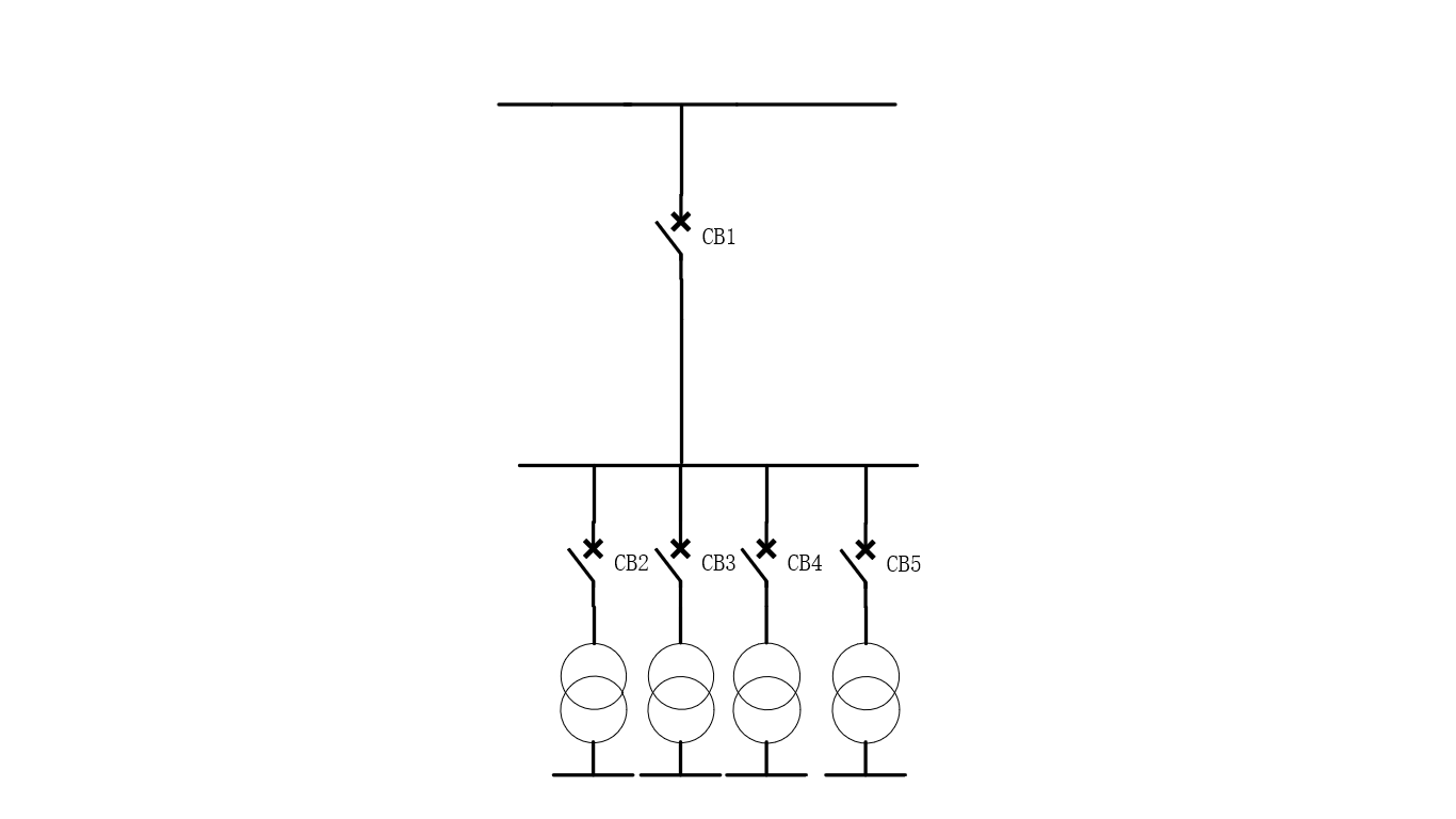
Simplified Site Wiring Diagram
The site operating condition involves using special transformers to step down the 10 kV power supply to 690 V and 400 V busbars, enabling different functions of various modules in the special equipment. During the on-site energization operation, circuit breakers CB2, CB3, CB4, and CB5 are kept in the closed position, and the four transformers are energized simultaneously through circuit breaker CB1.
After analyzing the site operating conditions and load characteristics, our company determined that in order to successfully energize multiple transformers without affecting the source-side circuit breaker, the overall closing inrush current of the special transformers must be suppressed to within 0.3 times.
To address this issue, our company provided an inrush current suppression cabinet solution. The inrush current suppression cabinet is connected in series with circuit breaker CB1 to suppress transformer energization magnetizing inrush current at the source, solving the switching challenges of special transformers and significantly improving switching success rate and operational stability.
Key challenges of the project: Multiple transformers needed to be energized simultaneously under the site operating conditions. The transformer magnetizing inrush current amplitude was high, requiring extremely high inrush current suppression performance. Traditional suppression methods provided limited effectiveness and were unable to meet the strict power stability requirements during on-site commissioning.
At the same time, the site had limited installation space, creating significant challenges for equipment integration and installation convenience. An efficient inrush current suppression function had to be achieved within a restricted space.
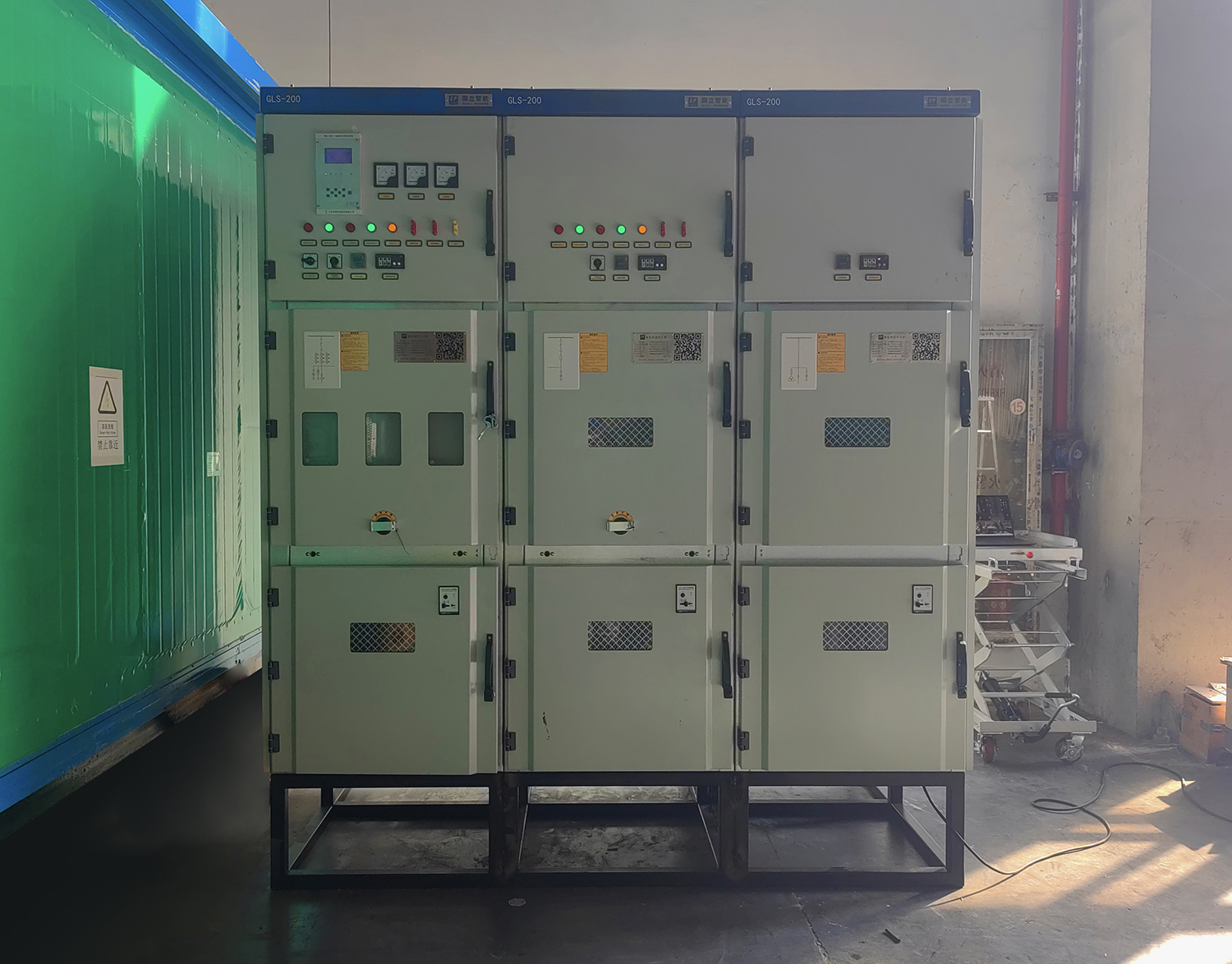
By using the inrush current suppression cabinet to reduce the closing impact of the special transformers, three switching operations were performed to energize the transformers. The data is shown in the table below:
PROJECT | MAXIMUM INRUSH | TRANSFORMER | ||
A | B | C | ||
FIRST‑CLOSING INRUSH CURRENT MULTIPLE | 0.25 times | 0.3 times | 0.3 times | One transformer energized |
FIRST‑CLOSING INRUSH CURRENT MULTIPLE | 0.18 times | 0.18 times | 0.14 times | Three transformers energized |
FIRST‑CLOSING INRUSH CURRENT MULTIPLE | 0.12 times | 0.10 times | 0.11 times | Four transformers energized |
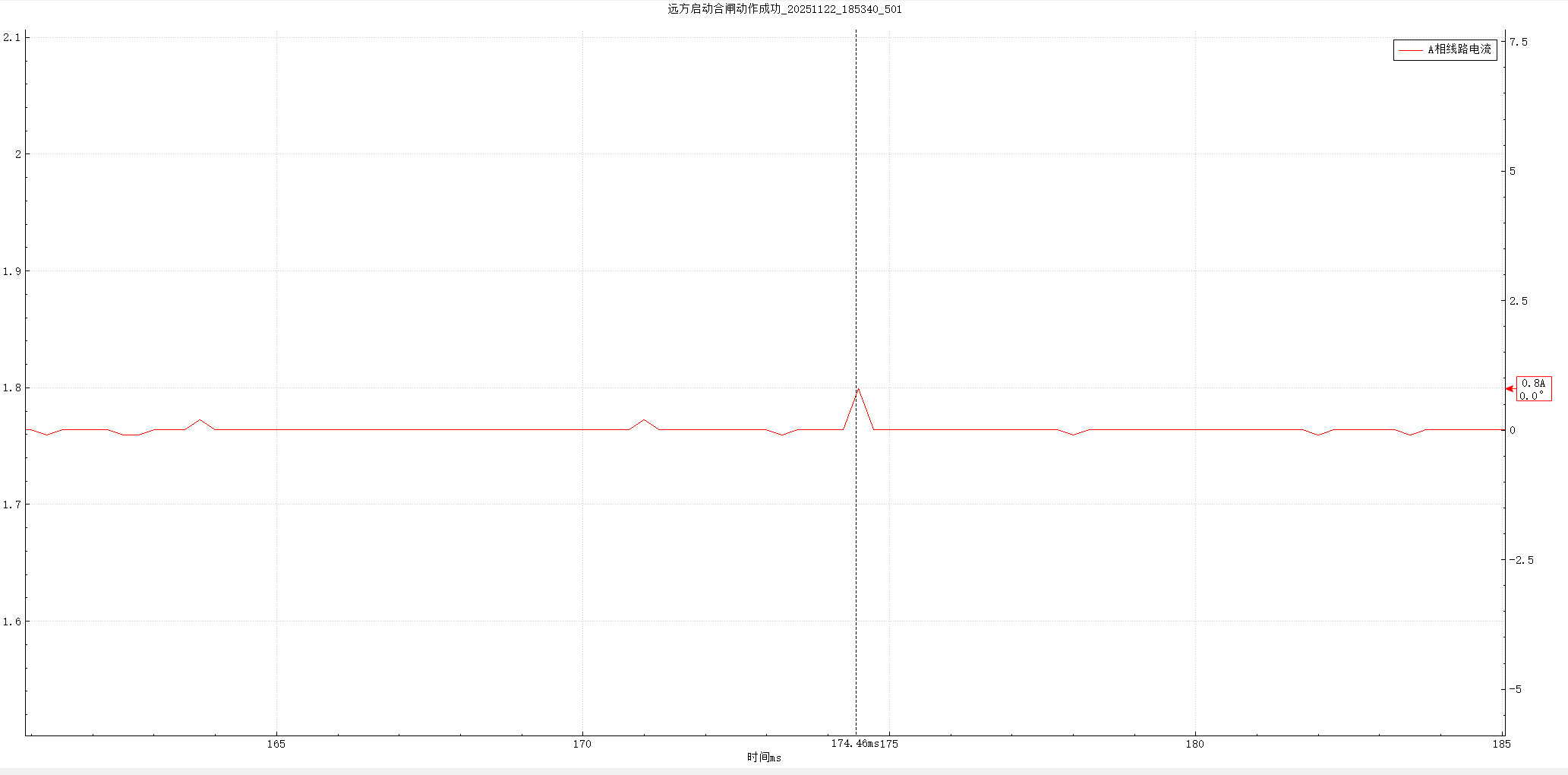
Actual Current Waveform
By applying the inrush current suppression cabinet to control the switching of the special transformers, the closing inrush current was suppressed to within 0.2 times the rated peak current during the simultaneous energization of up to four transformers. Meanwhile, the protection devices of the high-voltage switchgear in the special equipment production workshop and the grid-side circuit breaker remained inactive.
This achieved source-side suppression of transformer magnetizing inrush current during energization, solving power supply challenges during the production and operation of special equipment and ensuring reliable operation and continuous production.
The inrush current suppression cabinet solution is designed for special operating conditions with extremely strict inrush current requirements, including single or multiple special transformer switching, transformer energization with long cable connections, and “one-to-N” configurations.
The solution suppresses the generation of magnetizing inrush current at the source, significantly improving the switching success rate of special equipment and ensuring stable and reliable system operation.