Consult




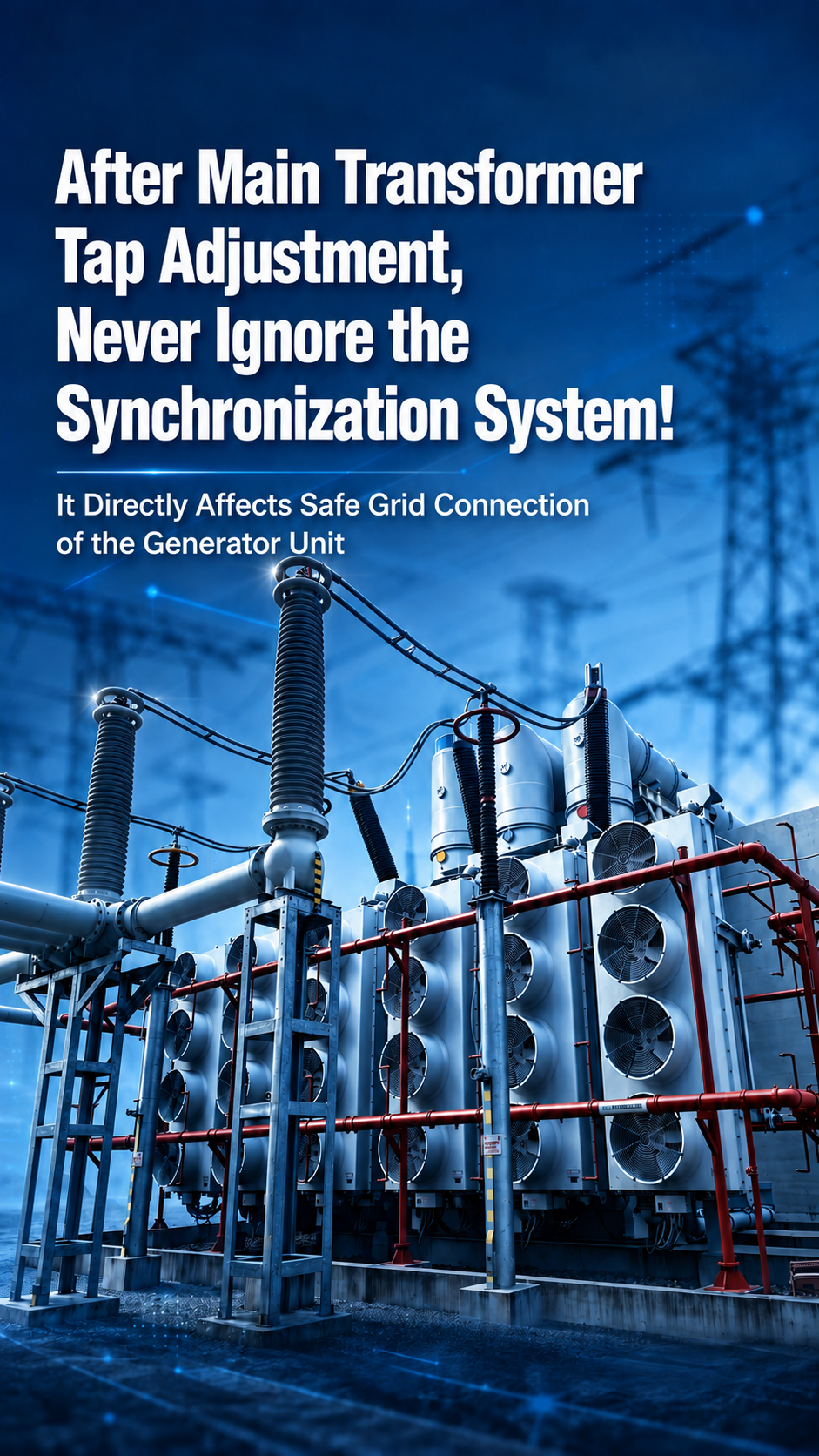
In the daily operation and maintenance of power plants, adjusting the tap changer of a main transformer is a routine operation: system voltage being too high or too low, load adjustment, circulating current balancing, and dispatch voltage regulation all call upon the on-load or off-load tap changing of the main transformer. Many crews tend to fall into a misconception: once the tap is changed, the voltage is normal, and the equipment sounds normal, the job is done. In fact, every tap change alters the transformer’s turns ratio, directly affecting the core conditions for synchronized grid connection.
Long-term neglect of verification can lead to failed grid connection, large inrush currents, unit vibration, and in severe cases, damage to the generator and the main transformer equipment.
Today we discuss: the core impact of main transformer tap changes on the synchronizing device, case illustration, and the recommended handling procedure — a must-read for frontline O&M, commissioning, and shift personnel.
PART 01 First, Understand: What Exactly Does a Main Transformer Tap Change Alter?
Core impact mechanism: turns ratio change → secondary rated voltage deviation
The core principle of main transformer voltage regulation is simple: by changing the number of turns of the HV winding, the turns ratio is adjusted, thereby changing the transformer’s output voltage.
1.1 The Principle of Tap Changing
The transformer changes the number of winding turns through the HV winding taps (tap changers), thereby adjusting the turns ratio and raising or lowering the secondary-side voltage.
Turns ratio calculation formula of the transformer:
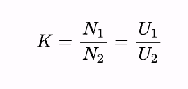
N1: number of turns of the transformer HV winding;
N2: number of turns of the transformer LV winding;
U1: transformer HV-side voltage;
U2: transformer LV-side voltage;
K: transformer turns ratio.
With the LV winding turns N2 fixed, changing the HV winding turns N1 changes the turns ratio K, thus regulating the transformer’s output voltage.
1.2 An Example for Illustration
The following figure is used for illustration: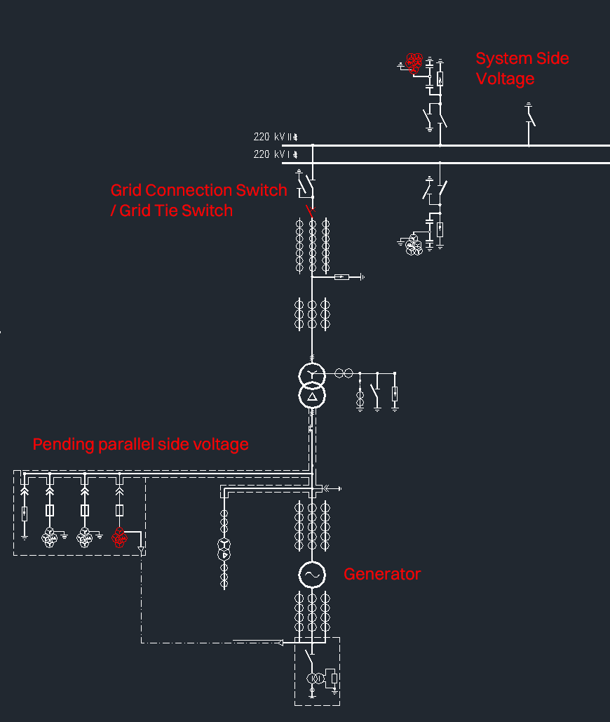
Figure 1 Single-line diagram of a certain power plant
As shown in Figure 1, the grid-connection switch of a certain power plant is the circuit breaker on the HV side of the main transformer. The voltage of the side to be synchronized (incoming side) of the synchronizing device is taken from the generator terminal PT, while the system-side voltage is taken from the 220 kV busbar PT. The main transformer parameters are given in Table 1.
Table 1 Partial nameplate parameters of the main transformer
Tap position | Ratio deviation |
Tap 5 | +5% |
Tap 4 | +2.5% |
Tap 3 | Rated |
Tap 2 | −2.5% |
Tap 1 | −5% |
System-side voltage: 220 kV busbar PT (PT ratio: 220 kV / 100 V)
Incoming-side voltage: generator terminal PT (PT ratio: 20 kV / 100 V)
Example:
When the main transformer operates at the rated tap, the HV- and LV-side voltages correspond to their respective rated values, and the PT rated voltage corresponding to the HV-side voltage serves as the reference base.
1. Moving to a higher tap (ratio deviation +2.5%): the HV-side voltage rises while the LV-side voltage remains unchanged. At this point, the PT rated voltage corresponding to the HV-side voltage shifts positively relative to the rated reference.
2. Moving to a lower tap (ratio deviation −2.5%): the HV-side voltage drops while the LV-side voltage remains unchanged. At this point, the PT rated voltage corresponding to the HV-side voltage shifts negatively relative to the rated reference.
The larger the tap number of the main transformer → the higher the HV-side rated voltage → the larger the turns ratio → the greater the deviation of the secondary rated voltage from the secondary PT rated voltage.
As soon as the main transformer changes tap, the turns ratio changes, and the system-side rated voltage of the synchronizing device is bound to deviate. If the initial rated-voltage setting of the synchronizing device was set based on the main transformer’s rated tap, then once the tap changes, its voltage parameter will deviate from the initial value.
PART 02 Core Impact
The system-side and incoming-side rated voltage settings of the synchronizing device are configured based on the measured values of the same-source phase-verification test, serving as the core reference for the device’s calculation of the grid-connection voltage difference.
Under the illustrated conditions, the synchronizing sampling voltage is directly affected by the main transformer’s tap position. After a tap change, if the settings of the synchronizing device are not re-checked in sync, the “settings may become disconnected from the operating conditions,” causing distortion in the device’s voltage-difference calculation and making the voltage-difference data displayed on the screen highly misleading. This directly invalidates the “allowable voltage difference” setting, leading to abnormal power fluctuations of the unit during synchronized grid connection, and even planting a major hidden hazard of non-synchronized paralleling.
PART 03 How to Adjust the Synchronizing Settings After a Tap Change?
To eliminate the safety hazard caused by voltage deviation, after the main transformer completes a tap change, the verification and correction procedure below can be followed:
· 1. Confirm that the synchronizing device’s voltages are taken from the PTs on the HV side (system side) and the LV side (incoming side) of the main transformer respectively, and clarify the corresponding sampling circuits.
· 2. Check and confirm the transformer tap baseline corresponding to the initial settings of the synchronizing device.
· 3. Based on the tap-to-rated-voltage relationship on the main transformer nameplate, have professional technical personnel calculate the voltage deviation at the current tap and match it with the discrimination logic of the synchronizing device.
· 4. After completing the setting adjustment, during the first grid connection with the new settings, simultaneously monitor the voltage matching between the system side and the incoming side displayed by the synchronizing device to verify the effectiveness of the adjustment.
Special note: if wiring has been newly added or changed in the synchronizing voltage circuit, grid connection may only proceed after ensuring that the phase sequence of the synchronizing voltage is correct, the synchronizing settings are error-free, and the false-synchronization test passes.
PART 04 End
A main transformer tap change may seem like a basic routine operation, yet it is closely related to unit grid-connection safety, equipment lifespan, and grid stability. Many major equipment failures and non-planned outage incidents originate from small details that were “habitually overlooked.” Only by standardizing every tap change and verifying every set of parameters can we hold the first line of defense for the safe and stable operation of the unit.
Important note: in addition to the above, we also have mature, field-proven solutions in the new-energy microgrid sector, helping enterprises transition smoothly toward the new power system:
Based on GoLead Intelligent’s 30+ years of technological heritage in power switching and transient surge suppression, the microgrid hybrid energy solution makes microgrid power supply more reliable and more efficient. Designed for multi-energy complementary microgrids combining wind, solar, storage, gas turbines and more, it solves the challenges of difficult multi-source coordination, demanding grid-connected/islanded switching, complex dispatch, and high O&M thresholds, delivering safe, efficient, and intelligent operation management and dispatch optimization.
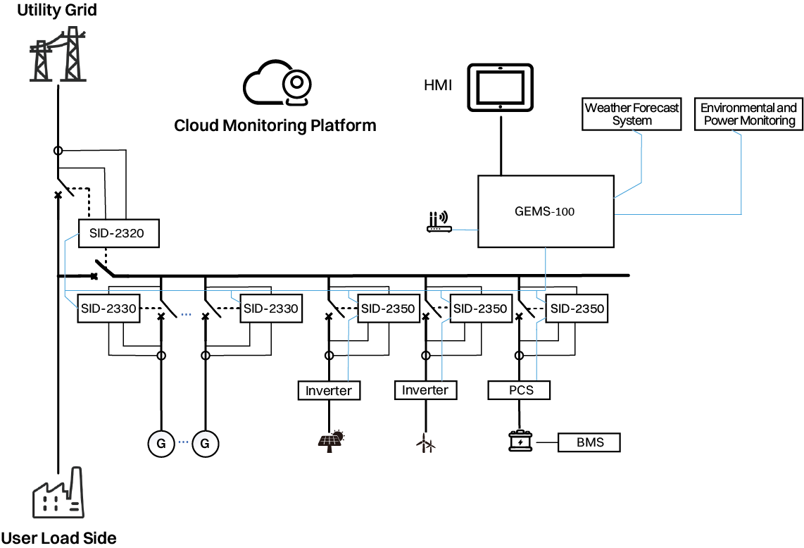
Microgrid hybrid energy management system with hierarchical control architecture
GEMS-100 Hybrid Energy Controller
Primarily used for energy systems composed of diesel or gas generating sets (“synchronous generating sets” for short), utility power, photovoltaic generation, wind power, energy storage, and other inverter-output power sources, it provides data acquisition, power and environment monitoring, and power dispatch strategy issuance. It can operate across a wide temperature range of −40°C to +85°C, adapting to complex environments.
SID-2300 Series Distributed Generation Control Terminal
The “safety gatekeeper” for grid connection of distributed generation, it flexibly adapts to diverse scenarios such as standalone operation, islanded grid connection, and 1+N parallel operation, achieving frequency/voltage/active-power/reactive-power monitoring and regulation on the source side, seamless switching in/out of emergency power, protection and control on both the utility side and the source side, and seamless grid-connected/islanded switching control. Backed by nearly 40 years of power control technology heritage, it safeguards safe switching control in distributed-generation and grid coordination scenarios.